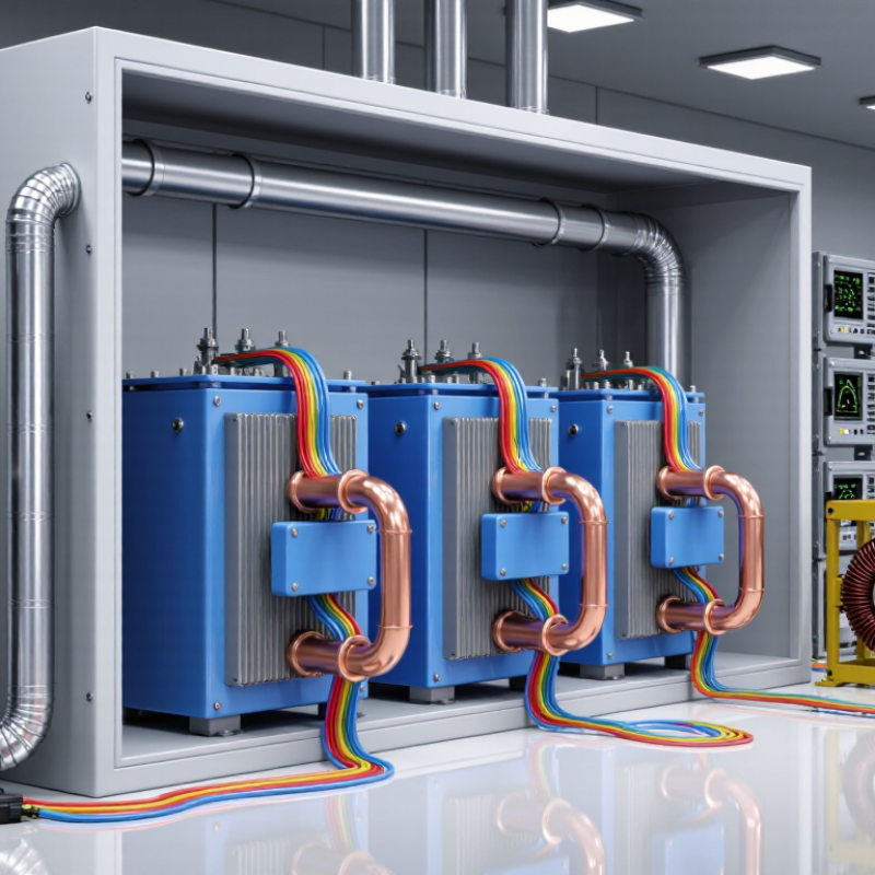
| Application type | Low-voltage shunt power-factor correction
Commonly used on three-phase industrial distribution systems. | IEC 60831-1 and IEC 60831-2 | Confirm whether the capacitor is intended for shunt power-factor correction rather than motor starting, filtering, coupling, or energy storage. | Use a capacitor designed specifically for the intended duty. A general-purpose capacitor should not automatically be substituted for a harmonic-filter or motor-capacitor application. | High |
| Rated system voltage | Select a rated voltage equal to or above the actual system voltage.
Typical low-voltage systems include 230 V, 400 V, 415 V, 480 V, and 690 V AC. | IEC 60831-1 for low-voltage shunt capacitors; IEC 60871-1 for higher-voltage applications | Measure the highest sustained line-to-line voltage, including transformer taps and utility variation. | Do not select only from the nominal voltage printed on the distribution panel. Consider voltage rise caused by harmonics, light loading, or overexcitation. | High |
| Frequency | 50 Hz or 60 Hz | IEC 60831-1; IEC 60871-1 | Confirm the capacitor frequency matches the power system frequency and that no variable-frequency drive output is connected directly to it. | Standard power-factor capacitors are normally connected on the line side of a drive. Do not connect them to a PWM motor output unless specifically designed for that service. | High |
| Required reactive power | Capacitor rating is normally expressed in kvar.
Approximate three-phase relationship:
kvar = √3 × VLL × IC / 1,000 | Electrical design calculation; manufacturer rating data | Measure real power, existing power factor, load profile, and target power factor before sizing. | For a target power factor, use:
QC = P × (tan φ1 − tan φ2).
Avoid excessive correction that can create leading power factor or overvoltage during light load. | High |
| Permitted voltage tolerance | IEC 60831 service limits commonly include short-duration overvoltage capability such as 1.10 UN for up to 8 hours per 24-hour period, subject to the applicable rating and conditions. | IEC 60831-1 | Check the exact overvoltage-duration table for the selected capacitor and compare it with measured system conditions. | Do not use the temporary overvoltage limit as a normal operating voltage. Persistent overvoltage significantly reduces capacitor life. | High |
| Permitted current and harmonic current | Many IEC low-voltage power capacitors are designed for a maximum continuous current around 1.3 times rated current, including the effects of harmonics, when the product rating specifies this value. | IEC 60831-1; capacitor manufacturer data | Measure RMS current, peak current, total harmonic distortion, and individual harmonic orders at the proposed connection point. | If nonlinear loads are present, choose a detuned reactor-capacitor system or a tuned filter based on a harmonic study. Do not rely only on the fundamental-frequency kvar calculation. | High |
| Resonance risk | Parallel resonance can occur when the capacitor bank and upstream system inductance create a resonant frequency near a dominant harmonic. | IEC 60831-1; IEC 61000 series for power-quality considerations | Identify six-pulse drives, rectifiers, welders, UPS systems, solar inverters, and other nonlinear loads. Review short-circuit power and existing capacitor banks. | Use detuned reactors where appropriate. A common design practice is a reactor detuning factor below the lowest significant harmonic, but the exact value must be calculated for the installation. | High |
| Discharge safety | The capacitor should include a discharge device that reduces residual voltage after disconnection in accordance with the applicable product standard. | IEC 60831-1; local electrical safety rules | Verify the specified discharge time, residual voltage, discharge resistors, contactor interlocking, and safe waiting time before access. | Provide visible isolation and lockout/tagout. Never assume that opening the contactor makes the capacitor safe to touch. | High |
| Internal fault protection | Select a capacitor with an approved overpressure disconnect or equivalent internal failure-limiting construction, where required by the product design. | IEC 60831-1 and IEC 60831-2 | Check internal protection, external fuse requirements, short-circuit withstand, and coordination with upstream protective devices. | Install current-limiting fuses or protective devices exactly as specified. Internal protection does not replace properly coordinated branch-circuit protection. | High |
| Temperature category | Common IEC temperature categories include lower limits such as −25 °C or −40 °C and upper limits such as +40 °C, +45 °C, +50 °C, or +55 °C, depending on the product category. | IEC 60831-1 | Calculate the enclosure ambient temperature, solar gain, nearby heat sources, ventilation performance, and daily temperature cycle. | Choose a temperature category that covers the real installation. Provide forced ventilation or thermal protection when enclosure temperature can exceed the rating. | High |
| Altitude | Standard equipment assumptions commonly use an installation altitude of approximately up to 1,000 m above sea level; higher elevations may require derating or special clearance review. | IEC 60831-1; IEC 60664-1 insulation-coordination principles | Record the actual site elevation and check air-clearance, creepage, cooling, and dielectric requirements. | For installations above 1,000 m, obtain the applicable altitude correction from the equipment documentation and electrical designer. | Medium |
| Enclosure and ingress protection | The enclosure IP rating must match the environment; examples include IP20 for protected indoor locations and higher ratings for dust, water, or outdoor exposure. | IEC 60529; local installation code | Assess dust, moisture, condensation, corrosive gases, salt exposure, vibration, and access by unqualified persons. | Use a suitable enclosure, gland system, heater, filter, or corrosion-resistant construction where environmental conditions require it. | High |
| Installation clearance and ventilation | Maintain the manufacturer’s minimum spacing around capacitors, reactors, fuses, and adjacent heat-producing equipment. | Manufacturer installation instructions; IEC 61439-1 for assemblies where applicable | Check airflow direction, top and bottom clearances, cable bending space, heat dissipation, and separation from control electronics. | Install capacitors upright when required, keep ventilation openings unobstructed, and prevent hot exhaust air from recirculating through the bank. | High |
| Switching method | Fixed banks, stepped automatic banks, capacitor-duty contactors, or electronic switching may be used depending on load variation. | IEC 60831-1; IEC 60947 series where applicable | Review switching frequency, inrush current, back-to-back bank conditions, discharge time between operations, and load transients. | Use capacitor-duty switching equipment and suitable inrush-current limiting reactors or resistors when required. Do not use ordinary motor contactors without checking suitability. | High |
| Automatic power-factor control | Controller step size should suit the load profile; typical banks may use equal or progressively larger steps. | Power-system design practice; controller documentation | Check response time, minimum step size, CT location and polarity, target power factor, and leading-power-factor prevention. | Place the current transformer so the controller measures the load and capacitor current correctly. Configure a minimum reconnection delay to allow discharge. | Medium |
| Insulation and dielectric test data | Verify rated insulation level, power-frequency withstand, impulse withstand where applicable, and routine test documentation. | IEC 60831-1; IEC 60871-1 for higher-voltage capacitors | Confirm the test voltage, insulation coordination, clearances, creepage distances, and compatibility with the switchboard assembly. | Use equipment with documented type and routine test results appropriate to the system voltage and installation category. | High |
| Maintenance and inspection | Periodic checks should include temperature, noise, swelling, leakage, fuse condition, terminal tightness, harmonic current, and power-factor performance. | IEC 60831-2; site maintenance program and local safety rules | Define inspection intervals based on load severity, temperature, dust, switching frequency, and criticality of the installation. | De-energize, isolate, lock out, verify absence of voltage, and allow the specified discharge time before inspection or service. | High |
| Documentation and compliance | Maintain the nameplate, wiring diagram, protection settings, test certificates, installation record, and harmonic-study results. | IEC 60831 series; applicable national electrical code and workplace safety legislation | Check that the product marking, declaration, test evidence, and installation instructions match the project specification and jurisdiction. | For projects commissioned in 2026, confirm the current adopted edition of each standard and any national deviations before procurement. | High |